More tire kicking to come, but I wanted to share my first genuine Heisenbug experience with F20 with you!
First, let me note that this didn't happen on the same system that I'd blogged about before - on that one I'd installed Fedora 20 Beta from scratch. This system is my "floortop" computer at home that was running Fedora 19 and which I just recently upgraded to F20 using FedUp.
Anyway, I was trying to open an existing account at mail.office365.com (yeah, I know) and FireFox 26.0 crashed 3 times in a row at the "loading your mailbox" point after logging in. I figured I'd be clever and start FF from a command line in a terminal, piping its console output to a file:
$ firefox &>office365FFdump.txt
Firefox "fired" up just fine. I pointed it to mail.office365.com, entered the login info and... found myself looking at the inbox, just as I did not expect. Just to be sure of what I witnessed, I logged out, closed FF and repeated the process. Again, success. So, attempting to observe Firefox fail, failed. So far it looks just like a Heisenbug!
Next things to (sanity) check:
- what does the default launcher pass to firefox's command line?
- what happens if I pass those same parameters (if any) to firefox when launched in a terminal?
I suppose there are a myriad of more aggressive debugging approaches I could take, but hey. This is just a passing chuckle so far - a demonstrative nod to this distro's codename.
Good night.
Followup:
When run from the default launcher, the only difference I can see between it and my running '$ firefox' from a terminal in my home directory is that the path to firefox in the launcher is explicit. Here's the result of me running it in my home directory but with the full path specified:
$ /usr/lib/firefox/firefox
(process:2465): GLib-CRITICAL **: g_slice_set_config: assertion 'sys_page_size == 0' failed
Segmentation fault (core dumped)
$
Hmmm, crashy.
Wednesday, December 18, 2013
Monday, December 9, 2013
Fedora 20 - Kicking the tires, pt 1
I've been playing with Fedora 20 (codename: Heisenbug) Beta and thought I'd share a few observations and impressions. As an aside, a heisenbug is an error in software code that can be difficult to track down because its buggy behavior changes or appears to just go away when you try to debug it. Let's hope the Fedora Project isn't saying their latest distro release is full of freaky, hard to track bugs!
Error: Package: boost-chrono-1.54.0-5.fc20.i686 (fedora)
Requires: boost-system = 1.54.0-5.fc20
Installed: boost-system-1.54.0-7.fc20.i686 (@updates-testing)
To correct those dependency problems, I had to do a couple of things. First replace the "newer" packages with the right stuff:
# yum distro-sync
Next was to disable the updates-testing repository for my machine so I wouldn't get into that kind of mess again:
# rm /etc/yum.repos.d/fedora-updates-testing.repo
A couple of friendly bits of advice: If you don't want to run into weird problems and just want a stable Fedora box, don't install a Beta release! The other thing is, if you do run into trouble, Google it first and if nothing turns up, you can hop on over to #fedora at irc.freenode.net and ask for help nicely. That's where I learned about "distro-sync".
Enabling a WiFi hotspot is a snap:
updates-testing
My first trip-up happened when I tried to install some software, specifically the "3D Printing" package group. By default when a Beta (not the final release) version of Fedora is installed, the "updates-testing" repository is enabled and when I did my first "# yum update", some packages were updated from the testing repo. When I tried to install the 3D printing group, boost (one of its dependencies) failed to install because it wanted specific versions of some other packages that had been replaced with "newer" versions from the updates-testing repo. Example:Error: Package: boost-chrono-1.54.0-5.fc20.i686 (fedora)
Requires: boost-system = 1.54.0-5.fc20
Installed: boost-system-1.54.0-7.fc20.i686 (@updates-testing)
To correct those dependency problems, I had to do a couple of things. First replace the "newer" packages with the right stuff:
# yum distro-sync
Next was to disable the updates-testing repository for my machine so I wouldn't get into that kind of mess again:
# rm /etc/yum.repos.d/fedora-updates-testing.repo
A couple of friendly bits of advice: If you don't want to run into weird problems and just want a stable Fedora box, don't install a Beta release! The other thing is, if you do run into trouble, Google it first and if nothing turns up, you can hop on over to #fedora at irc.freenode.net and ask for help nicely. That's where I learned about "distro-sync".
Wi-Fi Hotspot
Fedora 20 comes with a brand-new release of NetworkManager from the fine folks at gnome.org. One feature that I was interested in was the ability to easily create a WiFi hotspot. That turned out to be quite simple and "just worked". This nice thing about this latest release is that the hotspot is brought up in AP (master) mode if your Wi-Fi adapter supports it. Previously NM used adhoc mode, which most smartphones won't connect to because of security concerns. The Wi-Fi hotspot that NM creates for you does have a worrying security limitation in that it uses 40 bit WEP security. It takes just a few minutes to crack 40 bit WEP encryption. I popped into #nm at irc.freenode.net and mentioned this limitation. Immediately one of the devs there opened an issue in their bug tracker. Ain't Open Source great?Enabling a WiFi hotspot is a snap:
- Click in the upper left corner of the display
- Click on "Wi-Fi"
- Select "Wi-Fi Settings"
- Click "Use as Hotspot..."
- Click "Turn On"
- Done.
Tuesday, May 1, 2012
I2C Driver for the Raspberry Pi
I'm currently working on making a post on my blog writing a driver for the I2C buss controller(s) on the BCM2835 SoC that powers the Raspberry Pi. In a previous post, I mentioned the RoboCutter lawn robot my son and I are (sometimes) working on. I want it to have inclinometer, accelerometer and magnetic compass inputs and the only affordable, module level products I've found and like so far speak I2C. As I also said in a previous post, the R-Pi should be great as a high level controller for Mr. RoboCutter, but, R-Pi's SoC brain doesn't have a Linux driver for I2C at this point (that I know of), so I'm digging in to try to create one.
So far I've:
So far I've:
- Set up a cross-compiler toolchain to compile code for the Pi on x86 boxes I have on hand.
- Got the BCM2835 peripheral datasheet at ready reference
- Started coding a driver by examining existing Linux I2C drivers and using parts of a couple of them as templates. Having and having read and used the "Linux Device Drivers" book should help ;)
- Found two or three people who already have a Raspberry Pi who are willing and able to test driver code.
Friday, February 24, 2012
FRS Radio hack + Raspberry Pi?
If you've recently felt a disturbance in the techno Force, you may be sensing the arrival of the Raspberry Pi. The R-Pi, as some are calling it, is a credit card size computer based on a Broadcomm SoC (BCM2835) that boasts an ARM processor, a 2D/3D GPU, general purpose IO and runs Linux. Its stated purpose is to be a low-cost educational platform for youngsters, but its announcement has stirred up an amazing amount of interest in the streets of Nerdtown, Earth. At this writing, the first batch of 10,000 units aren't available yet, but I, like a few thousand others, am already planning what I'll do with it. That is, if I can get one.
Even though, cost-wise, it still makes more sense to use a cheap microcontroller in my planned FRS radio hack, I'm imagining the possibilities with a full-blown network stack and a Real(tm) operating system...
I've another project that I haven't mentioned here before that has me eyeing the Pi. The "Semi-autonomous Lawn Maintenance Platform" (aka RoboCutter) is a project that my son (11 at the time) and I started last year. It uses the wheel drive motors from a power chair (mobility scooter) and the Cypress Semiconductor PSoC that I alluded to in my previous radio hack post. The plan was to use the PSoC to do the low-level smarts such as power management, drive control, sickle bar control, etc. The higher level intelligence was planned to be a headless netbook computer running Linux, connecting back to a base station computer via WiFi. One problem with that plan is that, while I have a netbook, it's not headless and I don't want it to be! Well, the Raspberry Pi has all that handled, along with weight and power savings.
More on all of that later.
Sunday, November 20, 2011
Hacking FRS radios (walkie talkies)
Back in the early 90s, I got an 8 channel desktop scanner (radio receiver) on clearance at Radio Shack for about 20 bucks. The thing was real basic, with just a 7 segment LED display, no search capability and only 8 channels of "memory". I quickly got bored with just using it and decided to crack it open to see what made it tick. I was able to identify the microcontroller and another IC that I assumed was the PLL tuner. At the time, I didn't know much about PLLs and couldn't find the datasheet for the one in that radio, so I found one that was similar in function in a Motorola databook. After reading the datasheet and an appnote, I got to probing around on the radio. Long story short, I cut the traces between the PLL and the microcontroller and diverted the PLLs serial and other control lines to a 25 pin connector so it could interface with a PC via the printer port. I wrote a DOS based C program to control it and wound up with a 200 channel (about what I could fit on a 43 column VGA text screen) scanner with an automated, active frequency search function. That was a very educational 2 or 3 weeks I spent on it.
With my interest in amateur radio ramping back up recently, I decided to buy a pair of FRS/GMRS radios to check their ease of hacking for Ham use. FRS frequencies are very close to the amateur radio 70 cm band and I figured "all that's needed" is to tweak the frequencies a bit to be able to operate a really cheap transceiver for ham use. I bought a pair of Cobra brand MicroTalk model radios for $40. Before even powering them up, I took one apart to check the guts. Oh, then I googled "hack microtalk" and found this blog post. Not much active info or progress there, though.
When I dug into the MicroTalk radio I found the highly integrated AN29160AA transceiver IC from Matsushita (a different, Uniden radio is shown below which uses a AN29160A variant).

This chip does about everything except drive the display and handle the pushbutton inputs. Its functions, the PLL counters/divisors that set the tuning frequency as well as volume control and more, are operated by an external microcontroller through a 3 wire serial interface. My obstacles in attacking the MicroTalk radio were the very fine pitch surface mount leads and the fact that its microcontroller is hidden under the LCD display assembly. Not impossible to deal with, but tricky.
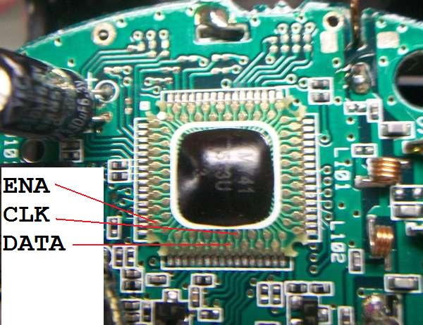
It occurred to me to check an older pair of Uniden brand FRS radios (model GMR638-2CK) that I already had. They actually turned out to not only use the same transceiver IC, but (in my opinion) to be a bit easier to hack. In this radio, the microcontroller was not buried under other stuff and even has handy little test point pads for every pin!

As you can see in the picture above, I've identified the basic signals that I need to hijack from the microcontroller. I may also need to monitor the squelch logic output and possibly provide an analog signal to generate tones. The earlier picture of the transceiver IC is also from the Uniden radio. Below is an o-scope snapshot of the DATA line being used while the radio was scanning FRS channels:

So far I've identified some necessary signals and the means to calculate the PLL counter values for arbitrary frequencies. Next I must plan what microcontroller I'll use to operate this thing, along with which other signals between the 29160 and the existing micro that must be hijacked or just piggyback onto. I also need to figure a clean way to put it all back together so that it can still be a handheld!
I may use Cypress Semiconductor's First Touch kit as the controller. It's a PSoC and probably way overkill, but for a few points: it's small, has all the IO I need and... I have one!
Check back later for more progress.
With my interest in amateur radio ramping back up recently, I decided to buy a pair of FRS/GMRS radios to check their ease of hacking for Ham use. FRS frequencies are very close to the amateur radio 70 cm band and I figured "all that's needed" is to tweak the frequencies a bit to be able to operate a really cheap transceiver for ham use. I bought a pair of Cobra brand MicroTalk model radios for $40. Before even powering them up, I took one apart to check the guts. Oh, then I googled "hack microtalk" and found this blog post. Not much active info or progress there, though.
When I dug into the MicroTalk radio I found the highly integrated AN29160AA transceiver IC from Matsushita (a different, Uniden radio is shown below which uses a AN29160A variant).

This chip does about everything except drive the display and handle the pushbutton inputs. Its functions, the PLL counters/divisors that set the tuning frequency as well as volume control and more, are operated by an external microcontroller through a 3 wire serial interface. My obstacles in attacking the MicroTalk radio were the very fine pitch surface mount leads and the fact that its microcontroller is hidden under the LCD display assembly. Not impossible to deal with, but tricky.
It occurred to me to check an older pair of Uniden brand FRS radios (model GMR638-2CK) that I already had. They actually turned out to not only use the same transceiver IC, but (in my opinion) to be a bit easier to hack. In this radio, the microcontroller was not buried under other stuff and even has handy little test point pads for every pin!
As you can see in the picture above, I've identified the basic signals that I need to hijack from the microcontroller. I may also need to monitor the squelch logic output and possibly provide an analog signal to generate tones. The earlier picture of the transceiver IC is also from the Uniden radio. Below is an o-scope snapshot of the DATA line being used while the radio was scanning FRS channels:

So far I've identified some necessary signals and the means to calculate the PLL counter values for arbitrary frequencies. Next I must plan what microcontroller I'll use to operate this thing, along with which other signals between the 29160 and the existing micro that must be hijacked or just piggyback onto. I also need to figure a clean way to put it all back together so that it can still be a handheld!
I may use Cypress Semiconductor's First Touch kit as the controller. It's a PSoC and probably way overkill, but for a few points: it's small, has all the IO I need and... I have one!
Check back later for more progress.
Wednesday, September 28, 2011
Overhead door sensor
A couple of months ago, one of my two garage door openers stopped cooperating. It acted like the light sensor/source pair that are supposed to detect when something or someone is in harm's way weren't working. The green LED on the sensor module wouldn't come on. So, after some weeks of ignoring the problem, I started digging into it.
First I opened up what turned out to be the source module - the one that provides the infrared light "beam" for the sensor to pick up. Not visible signs of problems there. Then I opened up the other one, the sensor module. After a few minutes of tracing out the circuit, I ran across the obvious. Can you spot it (click the pic to expand it)?

In case you missed it, there's a pin near the upper left corner of the board that isn't soldered in. That is the collector pin on a transistor. Pretty important connection to be made in most circuits. I guess this one was bent over far enough that it was contacting the pad on the PCB and had worked that way for untold years. ICs on various boards in the system have batch numbers from late 1997, the house was built in 1998 so the silly thing may have been working for as many as 12 or 13 years with this flaw. I figure either I, the cat or the kids wacked into it one time too many and jostled that delicate connection loose. Anyway, after a bout with the soldering iron, I put it back together and it works fine again.
This experience was similar to another one recently when the blower fan for the air handler in the central heat and air system stopped running. In that case, the fan control PCB's faulty connection *had* been soldered in, but the pad on the PCB apparently was not designed to handle the current. Over time, it melted away the solder first, then arced away at the remnants of the pad until it finally had nothing to arc to. Soldering a piece of 14 AWG wire across the right points took care of that one.
Funny thing, there - I knew exactly what to look for because precisely the same thing had happened at the "old house" a couple of years earlier. Took me about an hour the find and fix the first time and only 15 minutes the second time.
Tuesday, September 20, 2011
Cable ISPs
Incited by the topic of my previous post, I did a little hunting. The cable ISP I use at home bought a big chunk of their network, including that in my town, from the "upstream" ISP I mentioned earlier. I did a wee ping scan and found that I've been quite naive with respect to cable ISP security.
I discovered that at this ISP (and there's a bit of assumption here) all of the cable modems get a private IP in the 10/8 range in addition to the public and routable "WAN" IP that gets assigned to it. The unhappy part of this is that my cable modem's status web interface is available to anyone on my "local" ISP's network. If I thought about it all, previously, I guess I assumed that the CM's web interface was only local and not exposed to a fair chunk of the Net. Some cable modems only show their connection status, others provide a management login prompt... I imagine that many of them are still set to accept the manufacturers default password. This is on a network with potentially thousands of "local" users. The potential problems compound for those modems that double as wireless routers, such as mine. Once authenticated on it, one can navigate to a page that reveals the pre-shared key that is necessary to get past the WPA encryption on the WiFi side.
In case you want something to take home from this topic... if you have a cable ISP, lock down your modem by changing its default password. It may sound silly and simple, but while totally unsecured wireless routers are vulnerable to anyone who's out wardriving, your cable modem may be open to any basement dweller on your same ISP (or siphoning off a cable subscriber's WiFi).
"So?" you say. "At least the cable ISPs are limited in geographic and IP routing scope, so how much damage could be done?" Consider that pretty much *every* ISP currently has multiple subscribers whose computers are already infected with malware and may be part of a botnet. How much more difficult would it be for the bad guys to leverage an existing malware presence on your local cable ISP to wreak more harm? Plenty of room for clever, evil mischief.
Subscribe to:
Posts (Atom)